IR Control — The Invisible Frontier
How many of you grew up like me in a house with "the clicker"? Dad: "Steve, bring me the clicker. Perry Mason is about to start on channel eight… oh, thanks." ker-chunk, ker-chunk, ker-chunk… ker-chunk…Perhaps I was fortunate. Most of my friends didn't have "space command" in their homes. And, while the clicker didn't need batteries, we did have to replace the springs once in a while and put up with that motorized, ratcheting mechanical tuner. What if we couldn't find the clicker? Through her own early research and development in remote control, Mom discovered that if she took the large soup spoon and struck it with the paring knife she could change channels.
Thus began the era of the remote control in the home. In the US, most all remote controls for TVs began as ultrasonic (above human hearing) controls. These mechanical controls with limited functions evolved into electronic ultrasonic remotes with additional functionality. Then, in the late 1970s, infrared light became the method of choice when light emitting diodes became available. Why infrared? What is infrared exactly?
I Am, Therefore IR
The light emitting diode is a marvel. In the 70s, integrated circuit (IC) development was in its infancy. One of the curious byproducts of activated ICs was that some portions would emit light while operating. Researchers could see this strange light emission under laboratory conditions using electron microscopes. By the late 70s, semiconductor channel structures were designed to emit light when small voltage potentials were applied. While quite large compared to current fabrication technology, these silicon channel structures translate to wide gaps, or long wavelengths that can generate energy in the infrared, or what we call the IR region.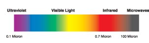
Figure 1. Infrared energy resides between visible
red and microwave radio.
This portion of the light spectrum is called "infrared" since it comprises the region between visible red and the microwave (radio) region. See Figure 1. The infrared region is relatively wide— extending from about 0.75 micrometers to over 100 micrometers. The most widely used infrared range for control is from 0.78 to 1.5 micrometers, or microns.
All objects not at 0° Kelvin (absolute zero) emit energy in the infrared region. Heat travels from one object to another via radiation, convection, or conduction. The sensation of heat is produced by infrared energy. While conduction describes how heat moves through a solid, convection describes how heat moves through a liquid or gas. Of the three methods, radiation is the most powerful. Radiation moves at the speed of light and is the phenomenon we perceive in the dull red glow of the coals in a fire or the element of an electric oven. Unlike visible light which can be refracted, filtered, or reflected, IR propagation may be modeled by some properties of visible light, but also propagates via radiation, convection, and conduction.
Not the Lone Radiator
I think of IR control as "the invisible frontier." Why? IR control is a land of unsettled territory. The trail is strewn with various digital control protocols and methods. Early makers of IR remote controls developed unique control protocols and chip sets for their products. Latecomers to IR control must decide whether to use an available protocol or develop yet another of their own design. Some system protocols are skeletons of others which, over time and out of the necessity to avoid control interference with other brands, branch out in different directions like the old desert mesquite. Meanwhile, most peaceful folk are amassing a vociferous collection of these ray guns; not to mention that each modern household now contains a new "junk drawer", a veritable mass grave, housing the "dead" IR remote controls… a kind of contemporary Boot Hill.At every turn of the system installation trail there can be outside interference in the form of IR noise, sunlight, fluorescent lighting fixtures, and heat sources. There are some organizations that, like the marshals of the old Wild West, are attempting to bring law and order in the form of standards to this necessary sector of systems control and integration. Who are these masked men?
One of them is IrDA-Infrared Data Association. This organization has developed standard intercommunications for two key application areas: data and control.
IrDA DATA
This is the popular two-way protocol for short range, high speed data exchange between enabled appliances, both portable and fixed installation. They claim application in over 300 million electronic devices currently. Data communication speed ranges from 9600 baud upwards in steps to 4 Mbps. This is a low power interface intended to auto-magically operate when two appliances are within range of one another…that range being at least one meter and upward of two meters. IrDA DATA is structured through a mandatory set of three protocols and a set of optional protocols. The optional set includes seven other functions providing specific exchange services and data handling facilities. Important attributes of this protocol set are automatic service discovery, device-to-device connection, data packet protection, and continuous bidirectional operation.IrDA Control
This variation allows cordless devices such as mice, keyboards, game pads, etc. to interact with host devices. Important aspects of this protocol are minimum five meter range, bi-directional communication, up to 75 Kbps transmission rate, protected data packets, and utilization of a 1.5 MHz subcarrier. Similar in design to IrDA DATA, IrDA CONTROL uses a mandatory set of three protocols: PHY (Physical layer), MAC (Media Access Control), and LLC (Logical Link Control).Even with new protocols and design improvements, every installation design using IR control must take into account the environment. IR receive sensors must be kept away from unwanted sources of ambient IR radiation, like sunlight exposure, incandescent lamps, and switched fluorescent light fixtures.
Infra-Shades
Ever wonder why infrared equipment typically has a dark red plastic window in front of the receiver? The receiver consists of a photodiode coupled with a bias circuit, a small amplifier, and perhaps, a demodulator. The photodiode's sensitivity curve, or optical bandwidth, includes the infrared region plus most, or all, of the visible spectrum, and possibly the ultraviolet portion as well. Allowing visible light and ultraviolet light energy to strike the photodiode will begin to make it conduct and, depending on the strength of these competing energy bands, will decrease the photodiode's sensitivity to infrared. If the diode is already in a conducting state due to other light energy, the incremental amount of response afforded by infrared reception may be incidental to the ambient current condition in the diode. The dark red filter blocks all ultraviolet and most all visible spectrum energy from reaching the photodiode. This situation returns the diode to a state of mild, or no, conduction until infrared energy passes through the red filter. Therefore, most all the diode's sensitivity is dedicated to infrared reception.Seeing Like An Owl
Some cameras and camcorders can capture images in total darkness. How does this work? As stated previously, photo diodes and the charge-coupled devices (CCDs) used in cameras respond to a wide range of photon wavelengths and any number of photons striking the surface of a photo sensitive semiconductor produces a proportional amount of electron charge.Camera CCD imagers may possess a spectral response from about 0.4 microns (blue) to about 1.050 microns (IR range). Additional processes will allow response to extend to the extreme ultraviolet range. Those who may own a popular camcorder that have the ability to shoot at night are utilizing such a device. The camcorder includes an IR LED that provides the IR light source for close range image capture. Additional illumination is obtained by the camera's sensitivity to the IR radiated by objects in its view.
Boulders Along The Trail
System designers have many control interface options. This article discusses IR control, but what about others? When would you want a hardwired interface over a wireless interface? Hardwiring a control interface is a good, solid approach when the presence or cost of wiring is not an issue, or the environment contains so many interference variables that may affect wireless operation. This type of control connection that makes use of the IR protocol is called an unmodulated IR system.Most times, IR control involves directionality. The IR transmitter must be pointed line-of-sight at the receiver within a few degrees of normal. So, some variability in control reliability can occur. Systems designed with IR flooding transmitters, repeaters, and wide angle transmitters and/or receivers tend to be less directional and can overcome this limitation to a great extent. Controlling any device within an environment of high ambient light, including unshielded incandescent light sources, can be challenging for an IR interface. Ambient light sources will tend to desensitize the IR receiver. Continuous levels of infrared ambient energy will cause the receiver's AGC system to decrease receiver gain, thus making the system less sensitive to remote IR transmitters.
Fluorescent lamps typically have not emitted large amounts of IR energy. Historically, fluorescent lamps have required rather large ballast transformers which develop enough high voltage to cause the fluorescent tube to ionize internal gases to create ultraviolet emissions that energize the phosphor coating on the glass. The light energy bands emitted by those lamps are not as rich in IR as incandescent lamps. Today, however, there are new, compact fluorescent lamps replacing incandescent light bulbs of various sizes. Many of these light bulb replacements are very compact. How does this affect IR control?
Drive power for these lamps is being generated by very compact switching power supplies operating as high speed power inverters. Much like a regular switch mode power supply, many of these power inverters operate around 40 KHz which is within the operating frequency of many IR systems. In addition, the switching frequency combining with small amounts of the lamp's IR energy create an interfering signal that may cause false triggering of IR-controlled systems. At a minimum, this energy can interfere with an IR control transmission that may confuse the IR receiver.
Playing Five-Card Protocol
There are about five common IR remote control system protocols. Each utilizes some format of modulated carrier for data encoding. Virtually all equipment manufacturers use one of the five protocols. The carrier frequency is typically between 30 – 40 KHz, with a large percentage of the remotes using 38 or 40 KHz. The use of the carrier supports the ability of the receiver to be tuned to that specific frequency, thereby enhancing the immunity of the system to external noise or interference. Most receivers are tuned to about +/- 2 KHz of the carrier frequency.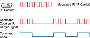
Figure 2. Data is transmitted via bursts of
carrier ON and carrier OFF.
Pulse Width Modulation (PWM) is commonly used to denote the difference between a data "1" and "0." In other words, the ON versus OFF time for communication of a zero is specifically different than that for a one. When the IR transmitter is actively communicating, it sends a burst of the carrier frequency that coincides with the required ON time followed by the required OFF time, or no burst, to signify either a one or zero. Refer to Figure 2 to see the relationship between the basic data and the way in which it is transmitted via modulated carrier. The number of cycles of carrier signal corresponding to the burst period representing the first part of a ONE or ZERO may be of the same time interval with the delineation between the two being the number of carrier cycles for which no burst is sent. The carrier burst ON time along with the carrier burst OFF time is called a "burst pair."Data bit timing is determined by taking the reciprocal of the carrier frequency and multiplying by the prescribed number of carrier cycles which represents a data bit. For example, the reciprocal of 38 KHz is about 26.3 microseconds (one carrier cycle). In one of the most popular IR remote protocols, a ONE is represented by 22 cycles of carrier ON followed by 96 cycles of carrier OFF. So, a logical ONE burst pair timing ratio is 22, 96. The zero burst pair is communicated by 22, 24. Therefore, the time to communicate a ONE is (22+96) x 26.3 µS = 3.1 ms and the time to send a ZERO is (22+24) x 26.3 µS = 1.2 ms.
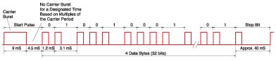
Figure 3. An example of an IR data transmission and its construction
Now, creating an actual transmission involves more than just sending the data. Most IR transmissions utilize a "start" pulse period to "wake up" the IR receivers and provide them the time to adjust to the incoming signal strength via their automatic gain control (AGC) circuit. Demodulation is optimized by setup of the system gain and this, in large part, is responsible for the system's noise immunity. In our example, the start pulse burst pair is 341, 171 which is a fairly long time interval, about 9 ms followed by 4.5 ms dead time. Following this start pulse are the data bits starting with the least significant bit (LSB) first. After all data bits are sent, there is a "stop" pulse burst pair of 22, 1427 which signifies the end of transmission. See Figure 3above.In this example, the full data transmission is constructed of four bytes. The first and second bytes signify the device address. The third byte identifies the function command and the fourth byte is the inverse of the third. The addition of the third with the fourth should equal 255. If this does not occur when the data is decoded, a transmission error is detected. Therefore, the entire transmission is 34 burst pairs including start, data, and stop bits. The total time required for the transmission varies depending on the complement of data ones and zeros. There is a nominal 40 ms rest period between transmissions. If a particular function key, say volume up, is continuously pressed, the transmitter may send a repeat command about every 180 MS. The receiver decides when to use the repeat command. Battery power is saved in the transmitter by using a repeat command code and not sending an entire code string when a key is held for long periods.
The receiver "sees" the carrier burst and, since we know that radio signal detectors convert a carrier without modulation to a DC voltage level, the output of the receiver's demodulator provides a high level when the carrier is detected and returns to low level when no carrier is detected. This is simple burst carrier demodulation. The microprocessor that ultimately must make sense of all the data bits looks for the large difference in data periods represented by the one and the zero. The fact that the time interval for a one is several times longer than a zero makes for easy recognition. Once detected, the data bits are processed like other data.
Long Live The Clicker
It seems wherever there is an electronic appliance today, there's an IR remote to operate it. How many remote controls do you own? IR control has become an essential commodity. And, even if we really don't need the remote control for every electronic gadget we buy, we think we do. Let's face it, IR remotes have changed the way we interface with electronic devices. The functionality expands and continues to improve. Imagine – now that we have low cost sound synthesis too, maybe we could incorporate that into these IR remote systems to re-create "the clicker" and the sound of that old motorized RF tuner... how technically nostalgic.
Infrared light and signals
IR Control — The Invisible Frontier
How many of you grew up like me in a house with "the clicker"? Dad: "Steve, bring me the clicker. Perry Mason is about to start on channel eight… oh, thanks." ker-chunk, ker-chunk, ker-chunk… ker-chunk…Perhaps I was fortunate. Most of my friends didn't have "space command" in their homes. And, while the clicker didn't need batteries, we did have to replace the springs once in a while and put up with that motorized, ratcheting mechanical tuner. What if we couldn't find the clicker? Through her own early research and development in remote control, Mom discovered that if she took the large soup spoon and struck it with the paring knife she could change channels.
Thus began the era of the remote control in the home. In the US, most all remote controls for TVs began as ultrasonic (above human hearing) controls. These mechanical controls with limited functions evolved into electronic ultrasonic remotes with additional functionality. Then, in the late 1970s, infrared light became the method of choice when light emitting diodes became available. Why infrared? What is infrared exactly?
I Am, Therefore IR
The light emitting diode is a marvel. In the 70s, integrated circuit (IC) development was in its infancy. One of the curious byproducts of activated ICs was that some portions would emit light while operating. Researchers could see this strange light emission under laboratory conditions using electron microscopes. By the late 70s, semiconductor channel structures were designed to emit light when small voltage potentials were applied. While quite large compared to current fabrication technology, these silicon channel structures translate to wide gaps, or long wavelengths that can generate energy in the infrared, or what we call the IR region.Figure 1. Infrared energy resides between visible
red and microwave radio.
This portion of the light spectrum is called "infrared" since it comprises the region between visible red and the microwave (radio) region. See Figure 1. The infrared region is relatively wide— extending from about 0.75 micrometers to over 100 micrometers. The most widely used infrared range for control is from 0.78 to 1.5 micrometers, or microns.
All objects not at 0° Kelvin (absolute zero) emit energy in the infrared region. Heat travels from one object to another via radiation, convection, or conduction. The sensation of heat is produced by infrared energy. While conduction describes how heat moves through a solid, convection describes how heat moves through a liquid or gas. Of the three methods, radiation is the most powerful. Radiation moves at the speed of light and is the phenomenon we perceive in the dull red glow of the coals in a fire or the element of an electric oven. Unlike visible light which can be refracted, filtered, or reflected, IR propagation may be modeled by some properties of visible light, but also propagates via radiation, convection, and conduction.
Not the Lone Radiator
I think of IR control as "the invisible frontier." Why? IR control is a land of unsettled territory. The trail is strewn with various digital control protocols and methods. Early makers of IR remote controls developed unique control protocols and chip sets for their products. Latecomers to IR control must decide whether to use an available protocol or develop yet another of their own design. Some system protocols are skeletons of others which, over time and out of the necessity to avoid control interference with other brands, branch out in different directions like the old desert mesquite. Meanwhile, most peaceful folk are amassing a vociferous collection of these ray guns; not to mention that each modern household now contains a new "junk drawer", a veritable mass grave, housing the "dead" IR remote controls… a kind of contemporary Boot Hill.At every turn of the system installation trail there can be outside interference in the form of IR noise, sunlight, fluorescent lighting fixtures, and heat sources. There are some organizations that, like the marshals of the old Wild West, are attempting to bring law and order in the form of standards to this necessary sector of systems control and integration. Who are these masked men?
One of them is IrDA-Infrared Data Association. This organization has developed standard intercommunications for two key application areas: data and control.
IrDA DATA
This is the popular two-way protocol for short range, high speed data exchange between enabled appliances, both portable and fixed installation. They claim application in over 300 million electronic devices currently. Data communication speed ranges from 9600 baud upwards in steps to 4 Mbps. This is a low power interface intended to auto-magically operate when two appliances are within range of one another…that range being at least one meter and upward of two meters. IrDA DATA is structured through a mandatory set of three protocols and a set of optional protocols. The optional set includes seven other functions providing specific exchange services and data handling facilities. Important attributes of this protocol set are automatic service discovery, device-to-device connection, data packet protection, and continuous bidirectional operation.IrDA Control
This variation allows cordless devices such as mice, keyboards, game pads, etc. to interact with host devices. Important aspects of this protocol are minimum five meter range, bi-directional communication, up to 75 Kbps transmission rate, protected data packets, and utilization of a 1.5 MHz subcarrier. Similar in design to IrDA DATA, IrDA CONTROL uses a mandatory set of three protocols: PHY (Physical layer), MAC (Media Access Control), and LLC (Logical Link Control).Even with new protocols and design improvements, every installation design using IR control must take into account the environment. IR receive sensors must be kept away from unwanted sources of ambient IR radiation, like sunlight exposure, incandescent lamps, and switched fluorescent light fixtures.
Infra-Shades
Ever wonder why infrared equipment typically has a dark red plastic window in front of the receiver? The receiver consists of a photodiode coupled with a bias circuit, a small amplifier, and perhaps, a demodulator. The photodiode's sensitivity curve, or optical bandwidth, includes the infrared region plus most, or all, of the visible spectrum, and possibly the ultraviolet portion as well. Allowing visible light and ultraviolet light energy to strike the photodiode will begin to make it conduct and, depending on the strength of these competing energy bands, will decrease the photodiode's sensitivity to infrared. If the diode is already in a conducting state due to other light energy, the incremental amount of response afforded by infrared reception may be incidental to the ambient current condition in the diode. The dark red filter blocks all ultraviolet and most all visible spectrum energy from reaching the photodiode. This situation returns the diode to a state of mild, or no, conduction until infrared energy passes through the red filter. Therefore, most all the diode's sensitivity is dedicated to infrared reception.Seeing Like An Owl
Some cameras and camcorders can capture images in total darkness. How does this work? As stated previously, photo diodes and the charge-coupled devices (CCDs) used in cameras respond to a wide range of photon wavelengths and any number of photons striking the surface of a photo sensitive semiconductor produces a proportional amount of electron charge.Camera CCD imagers may possess a spectral response from about 0.4 microns (blue) to about 1.050 microns (IR range). Additional processes will allow response to extend to the extreme ultraviolet range. Those who may own a popular camcorder that have the ability to shoot at night are utilizing such a device. The camcorder includes an IR LED that provides the IR light source for close range image capture. Additional illumination is obtained by the camera's sensitivity to the IR radiated by objects in its view.
Boulders Along The Trail
System designers have many control interface options. This article discusses IR control, but what about others? When would you want a hardwired interface over a wireless interface? Hardwiring a control interface is a good, solid approach when the presence or cost of wiring is not an issue, or the environment contains so many interference variables that may affect wireless operation. This type of control connection that makes use of the IR protocol is called an unmodulated IR system.Most times, IR control involves directionality. The IR transmitter must be pointed line-of-sight at the receiver within a few degrees of normal. So, some variability in control reliability can occur. Systems designed with IR flooding transmitters, repeaters, and wide angle transmitters and/or receivers tend to be less directional and can overcome this limitation to a great extent. Controlling any device within an environment of high ambient light, including unshielded incandescent light sources, can be challenging for an IR interface. Ambient light sources will tend to desensitize the IR receiver. Continuous levels of infrared ambient energy will cause the receiver's AGC system to decrease receiver gain, thus making the system less sensitive to remote IR transmitters.
Fluorescent lamps typically have not emitted large amounts of IR energy. Historically, fluorescent lamps have required rather large ballast transformers which develop enough high voltage to cause the fluorescent tube to ionize internal gases to create ultraviolet emissions that energize the phosphor coating on the glass. The light energy bands emitted by those lamps are not as rich in IR as incandescent lamps. Today, however, there are new, compact fluorescent lamps replacing incandescent light bulbs of various sizes. Many of these light bulb replacements are very compact. How does this affect IR control?
Drive power for these lamps is being generated by very compact switching power supplies operating as high speed power inverters. Much like a regular switch mode power supply, many of these power inverters operate around 40 KHz which is within the operating frequency of many IR systems. In addition, the switching frequency combining with small amounts of the lamp's IR energy create an interfering signal that may cause false triggering of IR-controlled systems. At a minimum, this energy can interfere with an IR control transmission that may confuse the IR receiver.
Playing Five-Card Protocol
There are about five common IR remote control system protocols. Each utilizes some format of modulated carrier for data encoding. Virtually all equipment manufacturers use one of the five protocols. The carrier frequency is typically between 30 – 40 KHz, with a large percentage of the remotes using 38 or 40 KHz. The use of the carrier supports the ability of the receiver to be tuned to that specific frequency, thereby enhancing the immunity of the system to external noise or interference. Most receivers are tuned to about +/- 2 KHz of the carrier frequency.Figure 2. Data is transmitted via bursts of
carrier ON and carrier OFF.
Pulse Width Modulation (PWM) is commonly used to denote the difference between a data "1" and "0." In other words, the ON versus OFF time for communication of a zero is specifically different than that for a one. When the IR transmitter is actively communicating, it sends a burst of the carrier frequency that coincides with the required ON time followed by the required OFF time, or no burst, to signify either a one or zero. Refer to Figure 2 to see the relationship between the basic data and the way in which it is transmitted via modulated carrier. The number of cycles of carrier signal corresponding to the burst period representing the first part of a ONE or ZERO may be of the same time interval with the delineation between the two being the number of carrier cycles for which no burst is sent. The carrier burst ON time along with the carrier burst OFF time is called a "burst pair."Data bit timing is determined by taking the reciprocal of the carrier frequency and multiplying by the prescribed number of carrier cycles which represents a data bit. For example, the reciprocal of 38 KHz is about 26.3 microseconds (one carrier cycle). In one of the most popular IR remote protocols, a ONE is represented by 22 cycles of carrier ON followed by 96 cycles of carrier OFF. So, a logical ONE burst pair timing ratio is 22, 96. The zero burst pair is communicated by 22, 24. Therefore, the time to communicate a ONE is (22+96) x 26.3 µS = 3.1 ms and the time to send a ZERO is (22+24) x 26.3 µS = 1.2 ms.
Figure 3. An example of an IR data transmission and its construction
Now, creating an actual transmission involves more than just sending the data. Most IR transmissions utilize a "start" pulse period to "wake up" the IR receivers and provide them the time to adjust to the incoming signal strength via their automatic gain control (AGC) circuit. Demodulation is optimized by setup of the system gain and this, in large part, is responsible for the system's noise immunity. In our example, the start pulse burst pair is 341, 171 which is a fairly long time interval, about 9 ms followed by 4.5 ms dead time. Following this start pulse are the data bits starting with the least significant bit (LSB) first. After all data bits are sent, there is a "stop" pulse burst pair of 22, 1427 which signifies the end of transmission. See Figure 3above.In this example, the full data transmission is constructed of four bytes. The first and second bytes signify the device address. The third byte identifies the function command and the fourth byte is the inverse of the third. The addition of the third with the fourth should equal 255. If this does not occur when the data is decoded, a transmission error is detected. Therefore, the entire transmission is 34 burst pairs including start, data, and stop bits. The total time required for the transmission varies depending on the complement of data ones and zeros. There is a nominal 40 ms rest period between transmissions. If a particular function key, say volume up, is continuously pressed, the transmitter may send a repeat command about every 180 MS. The receiver decides when to use the repeat command. Battery power is saved in the transmitter by using a repeat command code and not sending an entire code string when a key is held for long periods.
The receiver "sees" the carrier burst and, since we know that radio signal detectors convert a carrier without modulation to a DC voltage level, the output of the receiver's demodulator provides a high level when the carrier is detected and returns to low level when no carrier is detected. This is simple burst carrier demodulation. The microprocessor that ultimately must make sense of all the data bits looks for the large difference in data periods represented by the one and the zero. The fact that the time interval for a one is several times longer than a zero makes for easy recognition. Once detected, the data bits are processed like other data.
Long Live The Clicker
It seems wherever there is an electronic appliance today, there's an IR remote to operate it. How many remote controls do you own? IR control has become an essential commodity. And, even if we really don't need the remote control for every electronic gadget we buy, we think we do. Let's face it, IR remotes have changed the way we interface with electronic devices. The functionality expands and continues to improve. Imagine – now that we have low cost sound synthesis too, maybe we could incorporate that into these IR remote systems to re-create "the clicker" and the sound of that old motorized RF tuner... how technically nostalgic.
IR Control — The Invisible Frontier How many of you grew up like me in a house with "the clicker"? Dad: "Steve, bring me the clicker. Perry Mason is about to start on channel eight… oh, thanks." ker-chunk, ker-chunk, ker-chunk… ker-chunk… Perhaps I was fortunate. Most of my friends didn't have "space command" in their homes. And, while the clicker didn't need batteries, we did have to replace the springs once in a while and put up with that motorized, ratcheting mechanical tuner. What if we couldn't find the clicker? Through her own early research and development in remote control, Mom discovered that if she took the large soup spoon and struck it with the paring knife she could change channels. Thus began the era of the remote control in the home. In the US, most all remote controls for TVs began as ultrasonic (above human hearing) controls. These mechanical controls with limited functions evolved into electronic ultrasonic remotes with additional functionality. Then, in the late 1970s, infrared light became the method of choice when light emitting diodes became available. Why infrared? What is infrared exactly? I Am, Therefore IRThe light emitting diode is a marvel. In the 70s, integrated circuit (IC) development was in its infancy. One of the curious byproducts of activated ICs was that some portions would emit light while operating. Researchers could see this strange light emission under laboratory conditions using electron microscopes. By the late 70s, semiconductor channel structures were designed to emit light when small voltage potentials were applied. While quite large compared to current fabrication technology, these silicon channel structures translate to wide gaps, or long wavelengths that can generate energy in the infrared, or what we call the IR region.
This portion of the light spectrum is called "infrared" since it comprises the region between visible red and the microwave (radio) region. See Figure 1. The infrared region is relatively wide— extending from about 0.75 micrometers to over 100 micrometers. The most widely used infrared range for control is from 0.78 to 1.5 micrometers, or microns. All objects not at 0° Kelvin (absolute zero) emit energy in the infrared region. Heat travels from one object to another via radiation, convection, or conduction. The sensation of heat is produced by infrared energy. While conduction describes how heat moves through a solid, convection describes how heat moves through a liquid or gas. Of the three methods, radiation is the most powerful. Radiation moves at the speed of light and is the phenomenon we perceive in the dull red glow of the coals in a fire or the element of an electric oven. Unlike visible light which can be refracted, filtered, or reflected, IR propagation may be modeled by some properties of visible light, but also propagates via radiation, convection, and conduction. Not the Lone RadiatorI think of IR control as "the invisible frontier." Why? IR control is a land of unsettled territory. The trail is strewn with various digital control protocols and methods. Early makers of IR remote controls developed unique control protocols and chip sets for their products. Latecomers to IR control must decide whether to use an available protocol or develop yet another of their own design. Some system protocols are skeletons of others which, over time and out of the necessity to avoid control interference with other brands, branch out in different directions like the old desert mesquite. Meanwhile, most peaceful folk are amassing a vociferous collection of these ray guns; not to mention that each modern household now contains a new "junk drawer", a veritable mass grave, housing the "dead" IR remote controls… a kind of contemporary Boot Hill.At every turn of the system installation trail there can be outside interference in the form of IR noise, sunlight, fluorescent lighting fixtures, and heat sources. There are some organizations that, like the marshals of the old Wild West, are attempting to bring law and order in the form of standards to this necessary sector of systems control and integration. Who are these masked men? One of them is IrDA-Infrared Data Association. This organization has developed standard intercommunications for two key application areas: data and control. IrDA DATAThis is the popular two-way protocol for short range, high speed data exchange between enabled appliances, both portable and fixed installation. They claim application in over 300 million electronic devices currently. Data communication speed ranges from 9600 baud upwards in steps to 4 Mbps. This is a low power interface intended to auto-magically operate when two appliances are within range of one another…that range being at least one meter and upward of two meters. IrDA DATA is structured through a mandatory set of three protocols and a set of optional protocols. The optional set includes seven other functions providing specific exchange services and data handling facilities. Important attributes of this protocol set are automatic service discovery, device-to-device connection, data packet protection, and continuous bidirectional operation.IrDA ControlThis variation allows cordless devices such as mice, keyboards, game pads, etc. to interact with host devices. Important aspects of this protocol are minimum five meter range, bi-directional communication, up to 75 Kbps transmission rate, protected data packets, and utilization of a 1.5 MHz subcarrier. Similar in design to IrDA DATA, IrDA CONTROL uses a mandatory set of three protocols: PHY (Physical layer), MAC (Media Access Control), and LLC (Logical Link Control).Even with new protocols and design improvements, every installation design using IR control must take into account the environment. IR receive sensors must be kept away from unwanted sources of ambient IR radiation, like sunlight exposure, incandescent lamps, and switched fluorescent light fixtures. Infra-ShadesEver wonder why infrared equipment typically has a dark red plastic window in front of the receiver? The receiver consists of a photodiode coupled with a bias circuit, a small amplifier, and perhaps, a demodulator. The photodiode's sensitivity curve, or optical bandwidth, includes the infrared region plus most, or all, of the visible spectrum, and possibly the ultraviolet portion as well. Allowing visible light and ultraviolet light energy to strike the photodiode will begin to make it conduct and, depending on the strength of these competing energy bands, will decrease the photodiode's sensitivity to infrared. If the diode is already in a conducting state due to other light energy, the incremental amount of response afforded by infrared reception may be incidental to the ambient current condition in the diode. The dark red filter blocks all ultraviolet and most all visible spectrum energy from reaching the photodiode. This situation returns the diode to a state of mild, or no, conduction until infrared energy passes through the red filter. Therefore, most all the diode's sensitivity is dedicated to infrared reception.Seeing Like An OwlSome cameras and camcorders can capture images in total darkness. How does this work? As stated previously, photo diodes and the charge-coupled devices (CCDs) used in cameras respond to a wide range of photon wavelengths and any number of photons striking the surface of a photo sensitive semiconductor produces a proportional amount of electron charge.Camera CCD imagers may possess a spectral response from about 0.4 microns (blue) to about 1.050 microns (IR range). Additional processes will allow response to extend to the extreme ultraviolet range. Those who may own a popular camcorder that have the ability to shoot at night are utilizing such a device. The camcorder includes an IR LED that provides the IR light source for close range image capture. Additional illumination is obtained by the camera's sensitivity to the IR radiated by objects in its view. Boulders Along The TrailSystem designers have many control interface options. This article discusses IR control, but what about others? When would you want a hardwired interface over a wireless interface? Hardwiring a control interface is a good, solid approach when the presence or cost of wiring is not an issue, or the environment contains so many interference variables that may affect wireless operation. This type of control connection that makes use of the IR protocol is called an unmodulated IR system.Most times, IR control involves directionality. The IR transmitter must be pointed line-of-sight at the receiver within a few degrees of normal. So, some variability in control reliability can occur. Systems designed with IR flooding transmitters, repeaters, and wide angle transmitters and/or receivers tend to be less directional and can overcome this limitation to a great extent. Controlling any device within an environment of high ambient light, including unshielded incandescent light sources, can be challenging for an IR interface. Ambient light sources will tend to desensitize the IR receiver. Continuous levels of infrared ambient energy will cause the receiver's AGC system to decrease receiver gain, thus making the system less sensitive to remote IR transmitters. Fluorescent lamps typically have not emitted large amounts of IR energy. Historically, fluorescent lamps have required rather large ballast transformers which develop enough high voltage to cause the fluorescent tube to ionize internal gases to create ultraviolet emissions that energize the phosphor coating on the glass. The light energy bands emitted by those lamps are not as rich in IR as incandescent lamps. Today, however, there are new, compact fluorescent lamps replacing incandescent light bulbs of various sizes. Many of these light bulb replacements are very compact. How does this affect IR control? Drive power for these lamps is being generated by very compact switching power supplies operating as high speed power inverters. Much like a regular switch mode power supply, many of these power inverters operate around 40 KHz which is within the operating frequency of many IR systems. In addition, the switching frequency combining with small amounts of the lamp's IR energy create an interfering signal that may cause false triggering of IR-controlled systems. At a minimum, this energy can interfere with an IR control transmission that may confuse the IR receiver. Playing Five-Card ProtocolThere are about five common IR remote control system protocols. Each utilizes some format of modulated carrier for data encoding. Virtually all equipment manufacturers use one of the five protocols. The carrier frequency is typically between 30 – 40 KHz, with a large percentage of the remotes using 38 or 40 KHz. The use of the carrier supports the ability of the receiver to be tuned to that specific frequency, thereby enhancing the immunity of the system to external noise or interference. Most receivers are tuned to about +/- 2 KHz of the carrier frequency.
Data bit timing is determined by taking the reciprocal of the carrier frequency and multiplying by the prescribed number of carrier cycles which represents a data bit. For example, the reciprocal of 38 KHz is about 26.3 microseconds (one carrier cycle). In one of the most popular IR remote protocols, a ONE is represented by 22 cycles of carrier ON followed by 96 cycles of carrier OFF. So, a logical ONE burst pair timing ratio is 22, 96. The zero burst pair is communicated by 22, 24. Therefore, the time to communicate a ONE is (22+96) x 26.3 µS = 3.1 ms and the time to send a ZERO is (22+24) x 26.3 µS = 1.2 ms.
In this example, the full data transmission is constructed of four bytes. The first and second bytes signify the device address. The third byte identifies the function command and the fourth byte is the inverse of the third. The addition of the third with the fourth should equal 255. If this does not occur when the data is decoded, a transmission error is detected. Therefore, the entire transmission is 34 burst pairs including start, data, and stop bits. The total time required for the transmission varies depending on the complement of data ones and zeros. There is a nominal 40 ms rest period between transmissions. If a particular function key, say volume up, is continuously pressed, the transmitter may send a repeat command about every 180 MS. The receiver decides when to use the repeat command. Battery power is saved in the transmitter by using a repeat command code and not sending an entire code string when a key is held for long periods. The receiver "sees" the carrier burst and, since we know that radio signal detectors convert a carrier without modulation to a DC voltage level, the output of the receiver's demodulator provides a high level when the carrier is detected and returns to low level when no carrier is detected. This is simple burst carrier demodulation. The microprocessor that ultimately must make sense of all the data bits looks for the large difference in data periods represented by the one and the zero. The fact that the time interval for a one is several times longer than a zero makes for easy recognition. Once detected, the data bits are processed like other data. Long Live The ClickerIt seems wherever there is an electronic appliance today, there's an IR remote to operate it. How many remote controls do you own? IR control has become an essential commodity. And, even if we really don't need the remote control for every electronic gadget we buy, we think we do. Let's face it, IR remotes have changed the way we interface with electronic devices. The functionality expands and continues to improve. Imagine – now that we have low cost sound synthesis too, maybe we could incorporate that into these IR remote systems to re-create "the clicker" and the sound of that old motorized RF tuner... how technically nostalgic. |
| Since a long time the consumer electronics industy has been employing infrared remote controls for the control of television, VCR's and many other products. This same technic is popular In industrial- and officeapplications like control your pc to eliminate expensive keypads and cables. It's easier to use the infrared light than cables who always crossing each other. We humans can't see infrared light because the wavelenght of infrared light is below the visible spectrum(Some animals can see it and use it as a target for killing the prey). Because we don't see ir light we use it for remote control purposes. In remote controls the light source is a led but around us there are many objects who are emitting infrared light. The brighest source is the sun. In fact everything that radiates heat is also emitting ir light like flames, light bulbs, and even our body.  |
The only hardware you need for decoding IR signals is an infrared receiver. There are two main principles of ir remote controle: using a modulated beam at a frequency about 40kHz or the second is an non-modulated beam of IR light and has a restricted range.
The three layers of an infrared signal
Three typical layers are used by remote contrals. The names used for these layers has not been standardized. But we can call it the infrared, the modulation and the serial data.
The infrared layers is the means of transmission. We can't see infrared light because the wavelenght is too long to see. Altough you cannot see the infrared beam, it behaves the same as light, so if you can't see the target device, you can't control it with a ir remote control. To control applications through opaque materials, radiofrequency signals are used.

The modulation layer refers to the fact that each burst of infrared signal is often modulated at a frequency between 32.75 kHz and 56.8 kHz. This is done to diminish the effects of ambient light. This layer, however, is optional. Some infrared formats do not modulate their outputs, sending pulses of unmodulated infrared light instead. This is done to extend the remote control’s battery life and to reduce the cost of the remote control device.
The serial data layer has the information containing a command. This is typically coded in the lengths of infrared bursts or in the lengths of gaps between infrared bursts. Ex. A long gap or burst is interpreted as a '1', a short gap or burst is interpreted as a '0'.
Transmitting and receiving IR lights
Transmitting IR light is fairly simple done by using an infrared led. Like normal leds emmiting light waves in the visible ranges, ir leds are doing this with a light invisible for human eyes. But when you will see the ir beam, take a webcam and point the remote control to the cam and you will see a flashing light.
Receiving and decoding the signal is a lot harder. The ir light is captured by an ir sensitive photodiode with the highest spectral sensivity around 950nm.

The output signal is optical filtered, amplified and passed through a signal filter tuned to the frequency of the emitted signal frequency. The best and most easy to use are the integrated 3 leg ir receivers like the Vishay TSOP1836 and the Siemens SFH505A. The output of these devices is TTL compatible, the optical filter, amplifier with automatic gain control, tuned filter, and demodulator are integrated.
Phillips RC5 infrared remote protocol
| Most audio and video systems are equipped with an infrared remote control. |
| A common used standard protocol for infrared data communication is the RC5 code, originally |
| developed by Phillips. This code has an instruction set of 2048 different instructions and is divided into 32 address |
| of each 64 instructions. Every kind of equipment use his own address, |
| so this makes it possible to change the volume of the TV without change the volume of the hifi. |
| The transmitted code is a dataword wich consists of 14 bits and is defined as: |
| 2 startbits for the automatic gain control in the infrared receiver. |
| 1 toggle bit (change everytime when a new button is pressed on the ir transmitter) |
| 5 address bits for the systemaddress |
| 6 instructionbits for the pressed key |
The picture under are waveforms from my digital oscilloscope of rc5 codes with pushed buttons 1,2,3,4. You can good see the startbits and the toggle bit (These are inverted signals because they were captured directly on the TSOP1836). Read further for more info.
|
| The RC5 code uses the bifase modulation technic which means that every bit consists of 2 parts which are never the same. |
| So a bit is always a high/low or a low/high transisition. By the RC5 code a 1 is a low high transisition |
| and a 0 is high low transisition. For all the bits the most significant bit is transmitted first. |
| Remember also that the outputsignal of the integrated receivers is inverted: |
| Detecting an IR signal the output of the integrated receiver will be 0V. |
| The duration time of each bit is equal to 1,778 ms, and the total time of a full rc5 code is 24,778 ms. |
| The space between two transmitted codes is 50 bit times or 88,889ms. |
| To improve noise rejection the pulses are modulated at a carrier frequence |
| The carrier frequency of the rc5 code is 36 kHz so take always a receiver with a response |
| frequency of 36 kHz. |
| There are plenty of Detectors for receiving the bitstream of an IR remote control but the best |
| I ever used is the TSOP1836 of VISHAY. (Datasheet available on my site). |
The TSOP1836 is a 3 pin device that receives the infrared bursts and gives out the demodulated bitstream at the output. The RC5 code is an easy protocol to decode with a pic mircrocontroller . I will show an example to control your PC when it's finished |


| Panasonic's old infrared remote protocol |
| An other infrared remote protocol I will explain is an older Panasic remote protocol. | |||
| The protocol is similar with the RECS-80 protocol but it use more bits than the RECS-80 | |||
protocol. For the datatransmission Panasonic uses the pulse-place modulation. | |||
| For the communication a pulse is used with a fixed length, followed by a pause wich represents | |||
| the logical state of the bit. | |||
| 2048 codes are defined in this protocol, divided in 5 bits of custom code and 6 bits of data | |||
| code. The custom code is a value wich represents the manufacturer code and the data code | |||
| is a value wich represents the pressed button on the remote control. | |||
| The full transmitted code is 22 bits: First a header is sent then the custom code (5 bits), | |||
then the data code, followed by the inverse of the custom code and the invers of the data code, | |||
| and to terminate a stopbit is added to the code. | |||
| The invers transmitted bits are very usefull for the error detection. | |||
| Each first part of a bit is always a high level with a fixed time and is followed by a low level | |||
| where the time defines if the bit is a logic 1 or a logic 0. | |||
| Timing diagram: | |||
| T =420 µs to approx 424 µs in the USA and Canada | |||
| T=454 µs to approx 460 µs in Europe and others | |||
| The header is 8T high and 8T low | |||
A 1 is coded 2T high and 6T low | |||
| A 0 is coded 2T high and 2T low | |||
 | |||
| Daewoo infrared remote protocol |
| By the Daewoo protocol a logical 0 bit exists of a high puls with a duration time of 550 µs followed | |
| by a low puls of 450 µs this means that the total duration time of a logical zero bit is 1ms. | |
| A logical 1 bit is formed by a high on time of 550 µs followed by low signal of 1450 µs this means | |
| also that the total duration time of a logical one bit is 2 ms. | |
| The carrier frequency of the infrared signal is 38 kHz. When you will decode the signal with an | |
| integrated receiver module you need a receiver module wich is tuned on 38 kHz like the TSOP1838 | |
| fabricated by Vishay. It will function also with a 36 kHz module but the sensitivity is less than by a | |
| 38 kHz module. | |
| Because the receiver (mostly in hobby applications a microprocessor) needs to trigger on a new | |
| received code the protocol starts with a start bit of 8ms high level pulse and a 4 ms low level pulse. | |
| After this the 7 address bits and 7 command bits are sent. But the two words are divided by a 550µs | |
| high level signal and 4ms low level signal. Terminating the protocol is done with an another | |
| high level signal of 550µs. | |
| The time between two startbits of bitstreams when the button on the remote control is being pressed =60 ms. | |
 |
The sony ir code
| The Sony remote control is based on the Pulse-Width signal coding scheme. | |
| The code exists of 12 bits sent on a 40kHz carrier wave. The code starts with a header of 2,4ms or | |
| 4 times T where T is 600µS. The header is followed by 7 command bits and 5 adres bits. | |
| The address and commands exists of logical ones and zeros. A logical one is formed by | |
| a space of 600µS or 1T and a pulse of 1200 µS or 2T. A logical zero is formed by a space of 600 µS | |
| and pulse of 600µS. | |
| The space between 2 transmitted codes when a button is being pressed is 40mS | |
| The bits are transmitted least significant bits first. The total length of a bitstream is always 45ms. | |
The following bitmaps are waveforms measured with a digital oscilloscope. The signals were transmitted with a sony remote control
|


Decoding Sony IR protocol with a pic16f628
Today I'm started to write the firmware to decode ir signals because many people asked for it. On this page I will explain how I'm doing it with a pic16f628. The code will be written in assembler. Maybe later when I have good reactions on this topic I will publish my code of the tinyserirchip for the Phillips RC5 code.
Because many newbies and also hardcore electronists don't like it to make inmediatly huge printed circuit boards, so I will keep the hardware to a minimum that you can start with a breadboard (the way I did it to test the firmware), experimental pcb's.
These are the steps to do:
- Get the electronic components (cheap components approx. 10 Eur.)
- Place them on a pcb, schematic see further (Easiest and fast way is on a piece of experimental board)
- Programming a pic microcontroller or order one by me for 7 Eur (email me at davshomepage@pandora.be)
- Get a Sony remote control (12bit) or an universal remote control
- Here the fun can begin, see how the outputs toggle by pushing on the buttons of the infrared remote control
 | So whats the minimum: Because we work with IR light we need an ir receiver. The easiest way to receive modulated IR signals from remote controls is with an integrated module like those ones from Vishay or Siemens. I have the best experiences with the TSOP serie from Vishay. |
| Like you can read on my Sony IR protocol page the carrier frequency is 40kHz this means I use a TSOP1840. The output of this component is TTL compatible and we can connect it directly on an input pin of the microcontroller. To decode and translate the output datastream of the ir module we need a microcontroller, here I take a pic16f628. Because it's easy available for the hobbyist, very cheap (cheaper than the pic16f84) and I'm familar with programming pic chips. To make a visualisation when a valid ir code is received we need also a led. I toke a white led because i have many of them but when you change the resistor value you can take other colors. To do something with the received ir signals we need also outputs. The outputs are output pins of the microcontroller, we will use 8 of them to drive external power stages etc. |  |
| I will add also a function that sends the data to a computer. So it will be possible tocontrol your pc with the received infrared code. Then with a program running on the pc it will be possible to control winamp or other programs. At this moment the program will decode the sony protocol. When you push a button from 1..8 on a remote control you toggle the bits 0..7 on portB. When you push button 0 all outputs will be cleared. |

The component values are:
R1 if you use a white led 100ohm, if you use a normal led 270 ohm
C1 = 100nF
C2 = 10µF /16V
IR receiver = TSOP1840
CN1 = 8 pins header
The power supply is not included in the circuit, do a google websearch with the keyword 7805 voltage regulator and you will find hundreds of circuits.
Before you download the sourcecode I'm asking two little things:
- You don't rip the code (instead make a link to this page) and don't make money with it
| So whats the minimum: Because we work with IR light we need an ir receiver. The easiest way to receive modulated IR signals from remote controls is with an integrated module like those ones from Vishay or Siemens. I have the best experiences with the TSOP serie from Vishay. |
| Like you can read on my Sony IR protocol page the carrier frequency is 40kHz this means I use a TSOP1840. The output of this component is TTL compatible and we can connect it directly on an input pin of the microcontroller. To decode and translate the output datastream of the ir module we need a microcontroller, here I take a pic16f628. Because it's easy available for the hobbyist, very cheap (cheaper than the pic16f84) and I'm familar with programming pic chips. To make a visualisation when a valid ir code is received we need also a led. I toke a white led because i have many of them but when you change the resistor value you can take other colors. To do something with the received ir signals we need also outputs. The outputs are output pins of the microcontroller, we will use 8 of them to drive external power stages etc. | |
| I will add also a function that sends the data to a computer. So it will be possible tocontrol your pc with the received infrared code. Then with a program running on the pc it will be possible to control winamp or other programs. At this moment the program will decode the sony protocol. When you push a button from 1..8 on a remote control you toggle the bits 0..7 on portB. When you push button 0 all outputs will be cleared. |
The component values are:
R1 if you use a white led 100ohm, if you use a normal led 270 ohm
C1 = 100nF
C2 = 10µF /16V
IR receiver = TSOP1840
CN1 = 8 pins header
The power supply is not included in the circuit, do a google websearch with the keyword 7805 voltage regulator and you will find hundreds of circuits.
Before you download the sourcecode I'm asking two little things:
- You don't rip the code (instead make a link to this page) and don't make money with it
View the sourcecode:
Download the hexfile:
Many people asked me to change the code that it only responds to a specific address here you find this.
View the sourcecode:
Download the hexfile:
Below you can find a version for the pic16f84 you can activate also control the first four outputs and the last together with channel buttons.
With the volume buttons you toggle outputs 1,3,5,7 or 2,4,6,8.
View the sourcecode:
Download the hexfile:
Downloading the sourcecode and hexfile is free, but if you appreciate my work you can make a donation via paypal with the button below or take a look on the ads.
The pictures are send to by users who made this project, please send me your pictures to then I can publish them and encourage other people to build this nice project.
Ahmed Abd El-Rahman from Egypt his project.

| JVC infrared remote protocol |
| The JVC infrared remote protocol is almost equal to the daewoo protocol. | |
| It are just the timings and the spacer between the address and data bits who differs a little bit. | |
| By the JVC protocol a logical 0 bit exists of a high puls with a duration time of 600 µs followed | |
| by a low puls of 550 µs this. | |
| A logical 1 bit is formed by a high on time of 600 µs followed by low signal of 1600 µs. | |
| The carrier frequency of the infrared signal is 38 kHz. When you will decode the signal with an | |
| integrated receiver module you need a receiver module wich is tuned on 38 kHz like the TSOP1838 | |
| fabricated by Vishay. It will function also with a 36 kHz module but the sensitivity is less than by a | |
| 38 kHz module. | |
| Because the receiver (mostly in hobby applications a microprocessor) needs to trigger on a new | |
| received code the protocol starts with a start bit of 8ms high level pulse and a 4 ms low level pulse. | |
| After this the 7 address bits and 7 command bits are transmitted. | |
| Terminating the protocol is done with an another high level signal of 600µs. | |
| The time between two startbits of bitstreams when the button on the remote control is being pressed = | |
| 60 ms but the start header is only once transmitted in the beginning of the keypress. | |
 |
Tinyserir-RC5 |
| What is it? | ||
  | ||
| With thanks to Joop Van Schaik from the Netherlands for the pictures | Also thanks to Octavio Bru from Spain | |
| Datasheet: tinyeng.pdf | ||
| ||
| Tinyserir-RC5 is a tiny microcontroller, it's a pic12f629 microcontroller who has the firmware on board | ||
| for decoding RC5 infraredsignals and send them serial to a device with a RS232 communication port, | ||
| mostly a PC. | ||
| You can ask yourself, what can I realise with this chip, oh they're plenty of applications where you can | ||
| use the tinyserirchip, like controlling winamp with your infrared remote control while you are reading a book | ||
| There is chosen for the RS232 protocol because with the USB port today, the RS232 port is free and | ||
| have no futher function. | ||
| Like the name says the tinyserir-RC5 chip can decode infrared signals coming from an infraredreceiver. | ||
| The RC5 code is common used protocol originally developped by Philips (C) and still used by plenty of | ||
| brands for controlling there devices wireless. | ||
| When you don't have a RC5 remote controller you can use a universal remote controller which can be | ||
| 100% sure programmed to send RC5 codes. | ||
| Tinyserir decodes signals coming from an infrared receiver module wich is tuned for 36kHz. | ||
| An example of a compatible receiver is a TSOP1836 from Vishay. | ||
| The RS232 output pin is a pin who can be wired directly to a Basic stamp or via TTL-RS232 | ||
| level converter to a free serial port of the PC, and sends messages with a baudrate of 9600bps. | ||
| Tinyserir-RC5 sends exists of the following parts: A header wich indicates if it is a reset message or | ||
| an infrared message. | ||
| If it is a reset message, a header, the name and version number aretransmitted. If it is a message for | ||
| a received infrared code a header, the toggle bit, the address of the RC5 code and the command of the | ||
| RC5 code are transmitted. | ||
| The toggle bit indicates if a button on the remote control is being pressed or released during two | ||
| received codes. The address indicates if it is a TV or a satelite receiver or something else, and the | ||
| command indicates wich button is pressed on the remote control. | ||
| All the data which are transmitted via the rs232 pin are ASCII characters, so it is possible | ||
to view the codes in hyperterminal wich is standard included in Windows.
| ||
| The transmitted messages are clear and every part is easy to recognize for make it simple to decode the | ||
| messages with Delphi or visual basic. Many systems are decoding directly the output of the infrared receiver | ||
| but with these method your PC slower and less accurate because your system needs to poll the input in realtime what becomes a great problem for windows. But with the tinyserirchip your program only needs. | ||
| to read the ASCII characters in the serial input buffer of the RS232 port. | ||
| So you don't need to take care about the timing of the relative fast pulses (+-889 µS) or other processes who | ||
| are running on your system who can disturb the measuring of the infrared pulses. | ||
| Tinyserir sends only messages when a valid RC5 signal isreceived, this means when the timing of the | ||
| bitlengths are between the specifications and the bitphases are inverted, if not simply no message is | ||
| transmitted. | ||
| Following examples are the messages how they appear in hyperterminal or the input buffer as ascii | ||
| characters. | ||
| A reset messages looks like :R;Tinyserir-RC5;1.00; | ||
| The first character of the message is always the double point. The second is the header R when it's a | ||
| reset message. After this a seperator ";" the name of the chip and the version number of the firmware. | ||
| All the messages ends with a cariage return and a linefeed. | ||
| The header and the separate characters makes it easy to recognize the different parts of the messages. | ||
| The reset message is always transmitted as first after a reset of the chip. | ||
A message is also transmitted when a valid RC5 code is decoded. | ||
| The chip sends a messages like this: :C;1;000;006; | ||
| First the double point followed by the second character C to indicate it's a received RC5 code. | ||
| After this a separator and the toggle bit is transmitted. The toggle bit indicates if a button on the | ||
| remote control is being pressed or released between two received codes. | ||
| After this again a separator follows and 3 numbers to indicate the address of the rc5 code. This is 000 for a | ||
| TV remote control or a VCR is 005. After this a separator to end this part of the message followed by | ||
| 3 numbers which indicates the pressed button on the remote control.If we press for example on the | ||
| button 6 the tinyserir will transmit 006 followed by a separator and to end the message a carriage return | ||
| + a linefeed. (ASCII 13 + 10) | ||
| There are also two ledoutputs who can drive directly led's for some indication: like 1 led that blinks | ||
| with a fixed frequentie when the firmware is running and another led flashes when receiving infrared pulses. | ||
| How to order? | ||
| Order now one or more pieces by clicking on the buy now button. | ||
For the payment you need a Paypal account. | ||
| Customers from Belgium and Netherlands can order via the dutch page. | ||
| The chips are shipped in the next 3 workdays. | ||
| What's the price? | ||
| 1 piece : 9 Euro + shipment | ||
| Shipment: 5 Euro | ||
| Is there testsoftware available? | ||
| The first steps to see if your hardware works, can be done with hyperterminal or with the | ||
| following testprogram for windows 95/98/ME/XP. | ||
| Click here to download the testprogram | ||


4013, that the isolates from large voltages / currents. Inside the 3011 is an LED and a photo-transistor. The LED lights up when Q goes high, and in return the photo could transistor. Alternatively, the IC triggers a triac.
What I want to do is develop the setup to be triggered with the touch switches work or a facility managed by infrared.
Here is a diagram of the original circuit. I crossed the touch-switch on the top because they do not work properly. Now there are two resistors, capacitor, and a trigger for clock generation Schmit

![]()


.gif)
.gif)
.JPG)
.png)
.jpg)
.gif)
.JPG)

.jpg)
.jpg)


CM8870 DTMF decoder
ස්තාවර හෝ සෙලියුලර් දුරකතනයක් මගින් ලොකයේ ඔනැම තැනක සිටඋපකරන පාලනකිරිමෙ ඉතා සරල dtmf (Tone Decoder) ටොන් ඩ්කොඩර් පරිපතය
Cell Phone Controlled Door Latch


ඩ් ට් එම් එප් ගැනShort introduction to DTMF
DTMF means: Dual Tone Multi-Frequency, There is no baseband multiplexing done on DTMF signals. The signal generated by a DTMF encoder is a direct algebraic summation, in real time, of the amplitudes of two sine (cosine) waves of different frequencies. i.e. pressing '1' will send a tone made by adding 1209 Hz and 697 Hz to the other end of the line.
Here's a more detailed explanation of what DTMF is: Q: What frequencies do touch tones use for which numbers? A: The touch tone system uses pairs of tones to represent the various keys. There is a "low tone" and a "high tone" associated with each button (0 through 9, plus * (star) and # (octothorpe or pound symbol). The low tones vary according to what horizontal row the tone button is in, while the high tones correspond to the vertical column of the tone button. The tones and assignments are as follows:


When the 4 button is pressed, the 770 Hz and 1209 Hz tones are sent together. The telephone central office will then decode the number from this pair of tones. The tone frequencies were designed to avoid harmonics and other problems that could arise when two tones are sent and received. Accurate transmission from the phone and accurate decoding on the telephone company end are important. They may sound rather musical when dialed (and representations of many popular tunes are possible), but they are not intended to be so. The tones should all be +/- 1.5% of nominal. The high frequency tone should be at least as loud, and preferably louder than the low frequency. It may be as much as 4 db louder. This factor is referred to as "twist." If a Touchtone signal has +3db of twist, then the high frequency is 3 db louder than the low frequency. Negative twist is when the low frequency is louder.
It's been passed a lot of years since my first SMS remote control. The reason I stoped developing the source code of my previous circuit was that the T10s was not available in the market sinse a lot of years. So, people could not find very easy that cell phone to build the circuit. Two years later I built another one remote control based on GSM module. I choose the GM-47 Sony Ericsson module because it was very easy to handle it via AT commands. Moreover, the price was low enough for experiments. Finaly, I decided to release the source code under GNU General Public Licence V3 If you don't agree with the terms please DO NOT download or use any part of this project (schematic diagram, source code, hex code, PCB, etc).
Picture 1: The SMS remote controller
What is this circuit for?
With this circuit you can power-ON or Power-OFF a lot of electric/electronic devices such as aDSL modem, personal computers, water boilers, water pumps, garage doors, lights and many more. Moreover, you can watch the status of 8 switches. These switches can be connected with reed switches to the windows and the doors of your house. Just like a security system.
The circuit I have made has the following specifications:
- 4 relays to Power-ON or OFF any electronic/electric device.
- 8 digital inputs for reading normal swiches or reed switches.
- Very few and cheap components.
- SMS command execution is protected under a programmable password (for avoiding false SMS commands from other persons).
The schematic diagram.
This circuit is constituted by an AVR micro-controller (ATtiny2313) at 4MHz, the GM-47 GSM module, a SIM card and 4 relays. The GM-47 module works at 3.3V and is powered by the voltage stabilizer IC1 LM1117T 3.3. The micro-controller IC2 can work with power from 2.7V-5.5V when the speed is under 10MHz. So we power it at 3.3V because this is the voltage level that works GM-47 module. The data connection between GM-47 and ATtiny2313 is done at 9600 bps. The voltage level for this comunication is 3.3V from AVR's side and 2.7V from GM-47 side. Because of this voltage difference I used the T5 BC547 transistor to do the voltage level adaptation.
The connection of the SIM card with the GM-47 is been made by the SIM-holder K15 and the presence of the SIM card into the SIM-holder is been made by the swich SW on SIM-holder. The LED D6 when it flases, indicates that the connection to the cell phone network has been done properly. When the module cannot been connected to any cell phone network, the LED stays always ON (it's not blinking).
The GM-47 has digital and analog inputs-outputs it self but I didn't use them to avoid a malfunction with the danger of destroying the GSM module.
What the AVR micro-controller does.
After you power-on the circuit the IC2 (ATtiny2313) waits until GM-47 is initiallized, by reading the SIM card and connects to the GSM network that SIM card supports. After the connection to the network, the AVR sends the command to select the GM-47 memory as SMS storage memory. If the answer of the module is not
If there is an SMS, the AVR reads it and checks if there is the correct password. Initially the password is 1234 and can be changed by the user. Then, checks if the next character is the "*" (star). This symbol means: "Change the password with the following 4 numbers or letters". Then is searching to find the words . When "X" means the relay number (1-4) and "Y" means 0 or 1 (On or OFF). For example command means "Arm the 2nd relay" and means "Disarm the 3rd relay". After that the AVR checks again the SMS to see if there is the word
At the end the AVR deletes the SMS from the GM-47 first storage address and starts over sending again the AT commands .
Sending an SMS to the remote control
You can send an SMS from any cell phone to the remote control by following one of the above command syntax:
A) 1234*5678 Relay1=1 Relay2=0 Relay3=1 Relay4=1 Status
B) 1234 Relay1=1 Relay2=0 Relay3=1 Relay4=1 Status
C) 1234 1=1 2=0 3=1 4=1 Status
D) 1234 Status
E) 1234 Relay2=0
In case A we have the maximum of selections. We send the initial password 1234 and we change it to 5678. We arm the relay-1, relay-3, relay-4 and disarm the relay-2. Moreover, by writing the word
In case B we arm the relay-1, relay-3, relay-4, disarm the relay 2 and ask for the status of the relays and the switches.
In case C we do the same bypassing the words
In case D we ask only for the status of relays and switches.
In case E we change the status of only one relay. In this case relay-2 will be disarmed.
Piucture 5: The placement of the GM-47 module on the PCB. See the yellow thin film I put under the connector. This film is been put to protect the circuit from shortcuts between copper strip and the connector.
Download schematic, source code (in AVR assembly language), PCB.


introduction
With this circuit we can controll up to 8 devices (4 devices in our example project), by sending a specific SMS message with any mobile phone. Its very usefull at the cases that, at the place we have the devices, we have not a wired telephone line. If you have an old ericsson mobile phone and you are not using it, its the time to build some useful with that. The controlling that we can do to the devices, it is ON , OFF or Reset.
Usage of this circuit
With this circuit you can switch-ON , OFF or Restart some Linux servers, ADSL modems, Printers, Door with electric lock, Garage door, House lights, Water pumps, electric sunshade, Block the engine of your car or your motorcycle, at the steal case and much more. The purpose of this circuit is to make the human life better and easier.
The circuit
The hardware of the circuit its very very simple, because the communication port of ericsson mobile its working at the 5 volts with AT commands ( like the modem commands, but for mobile phones).
The firmware of the AT90S2313 (or ATtiny2313) its very complicated because, we have to convert the 'septets' of the phone to 'octets' because the AVR need bytes with 8 bits length ( The 'septet' is 1 byte with 7 bits length and 'octet' is 1 byte with 8 bits length). All this proccess its necessary to decode the message from SMS.
When you finish the circuit connect it to the mobile phone, turn on the phone and then power on the circuit, not before . The AVR now its trying to read the message from the 1st memory location of the phone, for that i suggest to delete all SMS messages from the phone before connect it to the circuit. If there is no message to the 1st memory location, the AVR its trying again until you sent any.
The format of the message must be only '1' or '0'. '1' to enable, or '0' to disable the device. The message must have only 8 numbers, '1' or '0' , alone or mixed .
Example: if you send the message 11000100 then you enable, starting from the right, the devices 3,7,8 ('1') and disabling the devices 1,2,4,5,6 ('0') .
If you want to send a new message and you don't want to change some device, must send the same number as the old message.
Example: If you want to enable only the 5th device, you must send a new message like 11010100 to keep the other devices as there are (we send the same message as the old ( 11000100 ) and we change only the 5th bit from '0' to '1' to enable the device ).
>> You can remove the
>> The PDU decode proccess. Take 7 bytes (8bits) and convert them to 8 bytes (8bits) by adding one zero at the start of each byte. The PDU format is use bytes with 7bit length.
Advice !
If you want to protect your devices from other person's messages, modify the source code, to read the AVR, your telephone number before execute any message. In the source code i have some part of code, to read the telephone number, the service center number, the date and the time of the received message.
The project its based on the Greek mobile phone network of
After the GSM receive the message, the AVR execute it, delete it from the phone memory, to release the 1st memory location and start again to search for a new message.
Service mode
If you connect the pin7 (PD3) of the AVR to MAX 232 chip and this to computer, you will see at the terminal window software, all the data that the GSM is send to the AVR (Sender's number, service center number, date, time and the AT commands ) . Setup the COM port to 19200 bps 8n1.
Troubleshoot
I have test it only with Greek sim cards and T10s mobile phone. I don't know if this circuit its working fine to other countries or other mobile phone models. You can build the diagnostic circuit that is in the dot frame of the schematic, and to connect the circuit with PC via RS232 port.
When you power-on the circuit and the phone, the AVR it will send the follow commands to the mobile phone:
1) AT+CPMS="ME" (Select the phone memory "ME")
and
2) AT+CMGR=1 (read the received message from memory possition 1)
If the mobile phone will response with:
AT+CMGR=1[CR][CR][LF] (this message its sended when there is no message in the phone memory)
+CMS ERROR: 500[CR][LF]
At this case the AVR it will send again the commands 1 & 2
If the mobile phone will response with:
AT+CMGR=1[CR][CR][LF] (this message its sended when a new message arrive in the phone memory)
+CMGR: 0,,26[CR][LF]
0791039624910000240C91xxxxxxxxxxxx00003001205151302108B1180C068BC162[CR][LF]
OK[CR][LF]
(xxxxxxxxxxxx is the phone number of the sender)
the AVR will decode the septets message to octets, execute it (arm or disarm the relays) and send the command
AT+CMGD=1 (delete the received message from memory possition 1)
to delete the message from the phone memory.
You can see the voltage of the PortB with any voltmeter if you have +5 or 0v voltage, to check if the command you send, for example"11001010", its executed.
History of SMS remote control (SMSrc):
03.12.2006
V2.2
- Plug 'n' play function: Some times the AVR stopped to communicate with T10s. Fixed!
24.08.2006
V2.1
- Reset command: Added a reset command. By sending the letter "r" or "R" , the AVR will disarm for 2 seconds the specific relay and then it will arm it again, until rext received SMS. It is perfect to reset ADSL modems, WiFi Access points, linux servers e.t.c.
- Transmition bytes to PC: The transmition pin has changed. Now the pin7 (PD3) is sending the data to PC, to see if the circuit is working propperly. The serial data communication has changed to 19200bps 8 none 1 .
- Problem with unrecognized characters is fixed. Now if you send SMS to T10s with any different character than "1" , "0", "r" and "R" , the AVR it will ignore it. At the previous versions (up to V2.0) when received any unknown character, the specific relay was went to
state. - Send response message: is removed because the cell phone provider is inform you for free, if SMS is delivered (this service in lot of countries is free).
The command method has not change it, you must send only up to 8 numbers '1' , '0' , 'r' and 'R' . For example 110r101R .
06.07.2004
V2.0 is now available. I have rewrite the code again from the start and I add 2 more features
- Plug 'n' play: now you can connect the SMSRC (SMS Remote Control) circuit with T10s mobile phone, power them ON both and then send any command '1' or '0' from some other mobile phone to the T10s of the circuit. The AVR will read the message and execute it and change the relay state.
- Send response message: when you send some command message from some other mobile phone (like nokia, siemens etc) to ericsson T10s like "11001010", the AVR will execute the command and then it will response to the sender's mobile phone, if command is executed.
The new code is more stable than the old one. The command method has not change it, you must send only 8 numbers '1' or '0' for example 11001010 .
23.10.2002
V1.0 is now available. You can control up to 8 devices by sending commands '1' or '0' . E
Downloads
| Download the source code and hex file of SMSremote control v2.2 |
| Download the source code and hex file of SMSremote control v2.1 |
| Download the source code and hex file of SMSremote control v2.0 |
| Download a small improved version of SMS remote controller with source code and the Hex files of project sms_controller.zip v1.01 |
| Download the schematic, source code and the Hex files of SMS remote controller project smscontroller.zip v1.0 |
Learn more about the Ericsson AT commands with ericsson T28 _R1A.zip file.
The pduspy.exe it's a software that you can controll the SMS memory of the smartcard or the SMS memory of the ericsson mobile phone via RS232 serial port of PC computer. For that, you need to buy (or to build your own) one data-cable to connect the phone with PC computer.


R1 = 470R
R2 = 100K
R3 = 3.3K
R4 = 10K
D1 = 1N4007
D2 = IR LED
Q1 = L14F1
RL = 5Vdc Relay
IC = CA3140
Q2 = BC548
Circuit Operation:
When regulated 5V is connected to the circuit, D2 emits infrared rays, which are received by phototransistor Q1 if it is properly aligned. The collector of Q1 is connected to non-inverting pin 3 of IC1. Inverting pin 2 of IC1 is connected to voltage-divider preset R4. Using preset R4 you can vary the reference voltage at pin 2, which also affects sensitivity of the phototransistor. Op-amp IC1 amplifies the signal received from the phototransistor. Resistor R3 controls the base current of transistor BC548 (Q2). The high output of IC1 at pin 6 drives transistor Q2 to energies relay RL1 and switch on the appliance, say, hand dryer, through the relay contacts. The working of the circuit is simple. In order to switch on the appliance, you simply interrupt the infrared rays falling on the phototransistor through your hand. During the interruption, the appliance remains on through the relay. When you remove your hand from the infrared beam, the appliance turns off through the relay. Assemble the circuit on any general-purpose PCB. Identify the resistors through colour coding or using the multimeter. Check the polarity and pin configuration of the IC and mount it using base. After soldering the circuit, connect +5V supply to the circuit.


For example, if you were watching TV, you could press and hold any button on the TV remote to trigger the circuit. In order not to change channel, you could press the button of the channel you are watching. You can connect anything to the relay, for example a lamp, but make sure that the relay contacts can handle the rated voltage and current.
Circuit Operation:
IC1 is an Infra Red module. IR modulated pulses are received and buffered by this IC. It has a standard TTL output, the output with no signal is held high by R1. A replacement for IR1 is the common TSOP1738 IR reciver. One gate of a CMOS inverter drives LED1 as a visible switching aid. Another gate buffers the signal and applies it to the time constant circuit, comprising R3,C2,R4 and D1. C2 charges via R3, and discharges via R4, D1 prevents quick discharge via the low output impedance of the CMOS buffer. If using a TSOP1738 then increase R4 to 470k.
The time taken to charge a capacitor is the product of resistance and capacitance, more commonly known as the RC time constant. At one RC a capacitor will only charge to 63% of the supply voltage. It takes 5 RC's for a capacitor to reach 99% charge. In this circuit the capacitor charge has to reach the logic threshold of the CMOS invertor. As the power supply is 5 Volts, the input threshold is around 3.6V, which takes about 3RC's or about 1.5 seconds. Once reached the inventor triggers the 555 timer and operates the flip flop. A simulation of received pulses, filtering and output pulse is shown below. Note that this is not from the actual circuit ( in which case the reconstructed pulse would be high for the duration of the 555 monostable) but only a spice simulation.
Parts List:
R1 3k3
R2 1k
R3 22k
R4 220k or 470k if using a TSOP1738
R5 1M
R6 3k3
B1 12 V
D1 1N4148
D2 1N4003
Q1 B109
LED1 CQX35A
IC1 IR1 available from Harrison Electronics or TSOP1838 or similar
IC2 4049
IC3 CA555
IC4 SN74HCT74 or SN74LS74
IC5 LM7805
Relay 12 Volt coil with changeover contact
C1 100u
C2 22u
C3 100n
C4 2u2
I would also like to thank Szabolcs Vrbos for his feedback about this circuit and pointing out a flaw in the drafting of the original schematic.


ස්තාවර හෝඡන්ගම දුරකතන භාව්තයෙන් උපකරන පාලනය කිරිමෙ පරිපත ( ඩ් ට් එම් එප් )
Remote Using Telephone
Here is a teleremote circuit which enables switching ‘on’ and ‘off’ of appliances through telephone lines. It can be used to switch appliances from any distance, overcoming the limited range of infrared and radio remote controls.
The circuit described here can be used to switch up to nine appliances (corresponding to the digits 1 through 9 of the telephone key-pad). The DTMF signals on telephone instrument are used as control signals. The digit ‘0’ in DTMF mode is used to toggle between the appliance mode and normal telephone operation mode. Thus the telephone can be used to switch on or switch off the appliances also while being used for normal conversation.
The circuit uses IC KT3170 (DTMF-to-BCD converter), 74154 (4-to-16-line demult-iplexer), and five CD4013 (D flip-flop) ICs. The working of the circuit is as follows.
Once a call is established (after hearing ring-back tone), dial ‘0’ in DTMF mode. IC1 decodes this as ‘1010,’ which is further demultiplexed by IC2 as output O10 (at pin 11) of IC2 (74154). The active low output of IC2, after inversion by an inverter gate of IC3 (CD4049), becomes logic 1. This is used to toggle flip-flop-1 (F/F-1) and relay RL1 is energised. Relay RL1 has two changeover contacts, RL1(a) and RL1(b). The energised RL1(a) contacts provide a 220-ohm loop across the telephone line while RL1(b) contacts inject a 10kHz tone on the line, which indicates to the caller that appliance mode has been selected. The 220-ohm loop on telephone line disconnects the ringer from the telephone line in the exchange. The line is now connected for appliance mode of operation.
If digit ‘0’ is not dialed (in DTMF) after establishing the call, the ring continues and the telephone can be used for normal conversation. After selection of the appliance mode of operation, if digit ‘1’ is dialed, it is decoded by IC1 and its output is ‘0001’. This BCD code is then demultiplexed by 4-to-16-line demultiplexer IC2 whose corresponding output, after inversion by a CD4049 inverter gate, goes to logic 1 state. This pulse toggles the corresponding flip-flop to alternate state. The flip-flop output is used to drive a relay (RL2) which can switch on or switch off the appliance connected through its contacts. By dialing other digits in a similar way, other appliances can also be switched ‘on’ or ‘off.’
Once the switching operation is over, the 220-ohm loop resistance and 10kHz tone needs to be removed from the telephone line. To achieve this, digit ‘0’ (in DTMF mode) is dialed again to toggle flip-flop-1 to de-energise relay RL1, which terminates the loop on line and the 10kHz tone is also disconnected. The telephone line is thus again set free to receive normal calls.This circuit is to be connected in parallel to the telephone instrument

1 TIL38 IR emitting diode
1 5mm Red LED
2 4.7M 1/4W resistors
1 1k 1/4W resistor
1 2.2k 1/4W resistor
1 27ohm 1/2W resistor
1 BC337 transistor
1 CA3140 MOSFET op-amp
The CA31340 is available in the US from part number N103140.
Current consumption 2mA standby 60mA operating ( with 12V supply)
2mA standby 85mA operating (with 15V supply)
IR receiver range <> 5 meters
It is difficult to measure the IR transmitter range as this is dependent upon a number of factors. The type of infra red control used and its proximity to the receiving photodiode, the voltage supply, the wavelength and efficiency of the IR emitter and the sensitivity of the controlled appliance all affect overall performance.
1) SH2030 diode was installed backward , this was an easy fix cause I used two pins of a 3 pin transistor socket instead of soldering the diode in place, it was easily reversed but the circuit still wouldn't work.
2) Was using a 120vac to 12vdc 300ma plug in transfomer that was putting out 16.8vdc. CHANGED this to a 9vdc 350ma unit that put out 13.0vdc and the unit worked just fine.
(You may want to include on your site that the extender is very sensitive to input voltage. I read on your site of someone else that had a similar problem and this was the corrective action.) Michael's MK1A is below:


.png)
.jpg)

අයි ආර් රිමොටයක් භාව්තයෙන් උපකරනයක් පාලනය කිරිම IR Remote Switch |
Imagine the convenience of selecting TV channels using your remote and then pointing the same remote to your switchboard to switch on/off the fan or the tubelight. Here is a simple circuit to remotely switch on/off any electrical device through a relay using the normal TV/VCR/VCP/VCD remote control unit. It works up to a distance of about 10 metres. |

send me exact circuit diagram of industrial electrical appliances control system using IR remote
ReplyDeleteI Could not found any MT/CM 8870 or KT3170 in Sri lanka Please help
ReplyDeletePlease help me about gsm on call to othet remote gsm calling
ReplyDelete
ReplyDeleteසුරේෂ් මහත්තයා මට දැන ගන්න පුලුවන්ද VHF radio රිසිවර් එකක් හදාගන්න කොමද කියලා
http://wordpress-blog17150.blogerus.com
ReplyDeleteNice information, valuable and excellent design, as share good stuff with good ideas and concepts, lots of great information and inspiration, both of which I need, thanks to offer such a helpful information,
ReplyDeletevisit this website
Nice information, valuable and excellent design, as share good stuff with good ideas and concepts, lots of great information and inspiration, both of which I need, thanks to offer such a helpful information,
ReplyDeletevisit this website
To Ardhanarishwara, the blissfully turing one who resides in the third eye plexus (Ajna Chakra) of each aspirant and who denotes the union of my Param Gurudeva Bhagwan Shiva and my Param Gurudevi Maa Shakti, are offered these salutions, prior this little student continues any further with the text,
ReplyDeleteFor more info visit: Shiva